Draw Hvac Plans Black and White Thermostat
In Article " Electrical Rules and Calculations for Air-Conditioning Systems – Part One ", which was the first Article in our new Class HVAC-ii: Electrical Rules and Calculations for Ac Systems, I explained the following points:
- Introduction for Air-Conditioning Systems Types,
Today, I will explain Electric Wiring for different Air conditioning Systems types.
Third: Electrical Wiring for Ac Systems
1- Importance Of Electric Wiring For Air conditioning Systems
In the detailed pattern phase, the electrical designer must size and select the wires/cables, conduits, starters, disconnects and switchgear necessary for supplying ability and control to HVAC equipment. This information designed by the electric designer will be and must announced on the electrical drawings for proper installation by the electrical contractor.
So, to determine the electrical equipment and power supply required for the HVAC system proper operation, the electrical designer needs:
- Knowing the size of the HVAC organisation (equipment types, locations, …),
- Understanding how different HVAC equipment operates in a sure HVAC organisation.
The above points can be fulfilled past agreement the electrical wiring diagram of private HVAC equipment and of the whole system also.
Notation:
Also the HVAC designer volition demand to know the size of the electric loads to assess the impact of the estrus generated by the electrical system on the HVAC load.
three- Types of Electrical Wiring Diagrams For Air-conditioning Systems
At that place are three basic types of wiring diagrams used in the HVAC/R industry today, which are:
- The Ladder Diagram,
- The Line Diagram,
- The installation diagram.
3.1 The Ladder Diagram
It is the well-nigh common blazon of wiring Diagrams. It is called ladder because the symbols that are used to represent the components in the system accept been placed on the rungs of a ladder. ladder diagrams will be referred to as "schematic" diagrams, or simply "schematics." A typical schematic of a packaged air conditioner is shown in Fig.3.
 |
| Fig.3 |
In electrical schematics, the symbols correspond various components in the circuit, and the lines correspond the wires connecting them. The intention of the overall schematic is to prove how the circuit functions, not how it actually looks.
Note:
A wiring schematic shows the condition of a piece of equipment when in that location is no power being applied to the unit of measurement. For example, if a switch is depicted as existence usually open (N/O) or normally airtight (N/C), remember that the position of the switch is shown as it appears when in that location is no power applied to that excursion. If at that place is any deviation from this do, there will exist an explanatory note on the schematic.
Earlier you begin looking at electrical schematic diagrams, though, retrieve that in that location are always five bones components to any schematic:
- A ability supply,
- A path for the power,
- A load or component that operates from the ability,
- A switch or component that interrupts the power to the load,
- A fable (meet Fig.4) or key that explains what the various symbols and abbreviations used in the wiring diagram.
 |
| Fig.4 |
3.2 The Line Diagram
- It ordinarily includes drawings that more closely resemble the components themselves, rather than symbols.
- Fig.v on the previous page is an example of a typical line diagram. Compare Fig.3 and Fig.5 and annotation the differences in the style that motors, switches, and transformers are represented. Today it is not uncommon for some manufacturers to show both types of diagrams on their equipment.
 |
| Fig.5 |
3.three The Installation Diagram
This diagram is used primarily by the installing contractor. Information technology usually shows simply what the concluding board connections are, and very rarely volition it include any internal wiring of the unit. Fig.6 is a typical installation diagram for a residential cooling system.
 |
| Fig.6 |
4- How to read Electrical Wiring Diagrams?
In lodge to read electric Schematics, you demand to be familiar with the following:
- Symbols Used In Schematics,
- Schematic Diagram Configurations,
- Schematic Diagram Locators.
4.1 Symbols Used In Schematics
The most of import symbols used in electrical schematics are:
- Power Supplies,
- Wiring,
- Switches,
- Loads.
A- Power Supplies:
Many different supply voltages are used in the HVAC/R manufacture, ranging from 575-5, three-stage ability supplies to 24-V control circuit voltages. Power supplies may be indicated by solid lines or by dashed or dotted lines.
 |
| Fig.seven |
B- Wiring:
- Most schematics use directly lines to represent the wires that connect components to each other.
- If ii wires are connected internally, the connexion usually is shown equally a dot (a solid black circumvolve), equally illustrated at those points marked "A" in Fig.viii.1. But annotation that at that place is no dot to betoken a junction or connectedness at bespeak "B." This means that one wire simply crosses over the other wire.
 |
| Fig.viii |
- Now expect at Fig.8.2, crossover wires are shown with half circles or loops that "jump" over other wires (meet those points marked "A"). Note besides that in this blazon of diagram, junctions are shown without connexion dots (see those points marked "B").
Notes:
- Not all manufacturers follow the same schematic diagram practices and you volition see several different styles of wiring diagrams.
- If dots are used to show junctions, then intersecting lines without dots mean that the 2 wires cross without connecting. If loops or jumps are used to depict crossovers, then wires that meet—even without dots—are continued.
Wiring identification:
Every manufacturer can identify the wires used in electrical diagrams by one of the following methods:
- Using Different line thicknesses to stand for unlike types of wires.
- Using numbers or colors (or both) to assistance place the various wires plant in a unit .
 |
| Fig.9 |
Note:
The used wiring identification method should exist conspicuously indicated in the legend that accompanies the cartoon.
C- Switches:
A switch is a device that interrupts power to the load. It may be:
- Manually Operated Switch,
- Activated automatically past pressure level or temperature (Control Switches),
- Electrically controlled switch (Relays and Contactors).
C.1 Manually Operated Switch:
The switch can be in the closed position (Normally closed) (North/C) or in the open position (Normally open) (Due north/O) (see Fig.10). You must notation that in electrical wiring schematic the position of the switch is shown as it appears when there is no power applied to that circuit. If at that place is any deviation from this practice, there volition be an explanatory note on the schematic.
 |
| Fig.10 |
A switch is characterized past :
- The number of contacts (or poles): the number of poles can be considered as the number of circuits that the switch can command at one fourth dimension or the number of contacts in the switch.
- The number of positions (or throws) information technology has: the number of throws tin be considered as the number of paths a unmarried excursion tin take.
 |
| Fig.11 |
Annotation:
The dashed line in the switch symbols represents the mechanical connection that makes the contacts move together, just these contacts are not connected electrically.
C.2 Activated automatically past pressure or temperature ( Control Switches) :
Pressure and temperature controls are switches; they also may be configured with various combinations of poles and throws.
The position of the switch "arm" in the schematic symbol indicates the performance of the command. for examples: (see Fig.12 )
 |
| Fig.12 |
- The temperature switch (RS-2) is shown with the arm to a higher place the contacts. This signifies that the switch opens on a rise in temperature and closes on a driblet in temperature.
- The pressure switch (AFS-2) is shown with the arm below the contacts. This signifies that the switch opens on a drop in pressure and closes on a rise in force per unit area.
- For SPDT limit switch (LS), When there is an increase in temperature, the contacts "C" to "North/C" move to the "N/O" position. When the temperature decreases, the contacts "C" to "North/O" motion back to the "N/C" position.
C.three Electrically Controlled Switch:
a- Relays:
- Relays are electrically operated control switches. The schematic symbols used to represent relays are the same as those for manually operated switches, except that relay symbols ofttimes include a solenoid coil.
- At that place are several possible ways of depicting the solenoid scroll. Fig.xiii shows 2 different schematic representations of a DPDT relay.
 |
| Fig.13 |
- Note that multiple-pole Relays, similar multiple-pole switches, are continued mechanically merely not electrically.
b- Contactors:
- A contactor is a type of heavy-duty relay that handles higher voltages and college currents than a control relay. Contactors appear nearly identical to relays on schematic diagrams.
- Some manufacturers utilize contactors that use a single set of contacts. A "charabanc bar" is placed over the connection where the other set up would be, as shown in Fig.xiv.
 |
| Fig.14 |
D- Loads:
Loads are devices that consume ability and convert it to another form of energy, such equally motion or rut. They may exist motors, heaters, lights, or other pieces of equipment. A transformer is a type of power-consuming device, merely rather than converting energy, a transformer changes the voltage or current.
 |
| Fig.xv |
four.ii Schematic Diagram Configurations
At that place are two bones configurations used in schematics today to evidence the judge placement of loads, switches, and different power or supply voltages. They are :
- Side-by-Side System,
- Upwards-and-Down Organization.
A- Side-past-Side Arrangement:
In this arrangement, Manufacturers normally place motors and other ability-consuming components on the right side of the diagram. This is called the load side. The switches and other controllers are placed on the left side of the diagram. This is called the line side.
 |
| Fig.16 |
B- Upwardly-and-Downwards Arrangement:
In this arrangement, the schematic is divided into:
- High-voltage section,
- Low-voltage section.
Normally the high-voltage department is placed at the peak of the diagram, and the low-voltage department is placed at the bottom of the diagram (see Figure 10). The vertical lines at the outer edges of the diagram represent the source of electrical power. All control devices and load devices are located on the horizontal lines betwixt these outer vertical lines.
An easy way to make up one's mind the different voltages in this blazon of schematic is to look for the transformer. Information technology normally is the dividing line for voltage changes.
Fig.17 shows many of the schematic symbols used in the HVAC/R industry today.
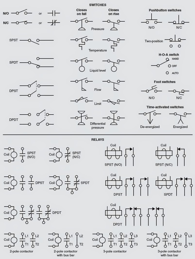

 |
| Fig.17 |
4.three Schematic Diagram Locators
As in roadmaps, almost all mapmakers place numbers and/or letters along the vertical and horizontal edges of maps to assist users discover particular cities, towns, landmarks, or other locations. Electrical schematics utilize a similar system.
Take a look at Fig.18. This is the same schematic of a packaged air conditioner that you saw in Fig.three, simply detect that now a column of small numbers has been added, running down the left hand side of the diagram. These numbers are used to indicate the relative location of each horizontal line in the diagram.
 |
| Fig.eighteen |
Note:
If a line falls between two numbers, the number lower on the page more often than not is used as the location reference.
This type of line-numbering system tin be very useful in helping the reader identify the location of a specific component on the schematic, likewise as its controlling switch. For examples:
 |
| Fig.nineteen |
A- Numbers on Left hand side of the diagram:
In Fig.19A, "C1" contacts are located on lines seven and xi. Similarly, in Fig.19B, yous tin find the loftier voltage switches "IFR" and "C1" on lines 28 and 35, respectively. Now look at the lower portion of the wiring diagram in Fig.18 and locate the relay coils "IFR" and "C1" on lines 52 and 57.
B- Numbers on Right hand side of the diagram:
In Fig.19C, note that there are minor numbers forth the right hand side of the diagram as well. These numbers designate the line location of relay contacts. The small number 28 in the correct-hand margin tells you the line location of the contacts associated with relay coil "IFR." Look back at line 28 in Fig.19B, and you lot will find the "IFR" contacts. Likewise, the numbers 7, 11, and 35 in the right-mitt margin of Fig.19C refer you to the lines where the contacts associated with relay curlicue "C1" tin be plant.
C- Underlined Numbers:
Annotation that the 35 is underlined. An underlined number signifies a normally closed contact (and, conversely, a number that is not underlined signifies a usually open up contact). Accordingly, you volition discover that the "C1" contacts located on line 35 in Fig.19B are shown as normally closed, and that the "C1" contacts on lines vii and xi in Fig.19A are shown every bit normally open.
In the next Article, I will explain Electrical Wiring Diagrams for different Air-Conditioning Systems Types and Equipment. So, please keep post-obit.
Source: http://www.electrical-knowhow.com/2014/05/How-to-read-Electrical-Wiring-Diagrams.html